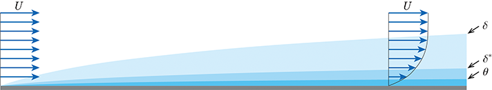
Boundary-Layer Thickness Definitions
An additional parameter, known as shape factor and usually denoted by $H$, helps describe the shape of the boundary-layer velocity profile. It is defined as the ratio of displacement thickness to momentum thickness
$$
H=\frac{\delta^{*}}{\theta}
$$
All these parameters depend only on the velocity profile inside the boundary layer. We can simply evaluate their magnitudes by assuming that the velocity profile inside the laminar boundary layer satisfies the quadratic curve
$$
\frac{u}{U}=a+b\!\left(\frac{y}{\delta}\right)+c\!\left(\frac{y}{\delta}\right)^{2}
$$
The values of the coefficients are determined by the boundary conditions at the wall and outer edge of the boundary layer:
- At the wall $(y=0)\!$ : $u=0$
- At the outer edge of the boundary layer $(y=\delta)\!$ : $u=U,\quad \partial u/\partial y=0$
Substituting the above formula into Equations \(\boxed{\delta^{*}=\int_{0}^{\infty}\!\left(1-\frac{u}{U}\right)\,dy}\), \(\boxed{\theta=\int_{0}^{\infty}\!\frac{u}{U}\!\left(1-\frac{u}{U}\right)dy}\) and \(\boxed{H=\frac{\delta^{*}}{\theta}}\), and setting the upper limit to be \(\delta\)
$$
\delta^{*}=\frac{1}{3}\,\delta,\qquad
\theta=\frac{1}{7.5}\,\delta,\qquad
H=2.5
$$
1Hongwei Wang (2023). A Guide to Fluid Mechanics. National Defense Industry Press.